Understanding the Problem: DPF Full and Regeneration Failures
AECS Equipment Technical Support was recently presented a case from one of our equipment owners. The following story is how this issue was worked through by the workshop and our team..
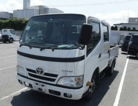
Toyota Dyna 2014
The problem presented to the support team was a Toyota Dyna 2014 with a
DPF( Diesel particulate filter ) showing full and requiring regeneration. The driver of this fleet vehicle had carried out a regeneration, only to travel for another hour on the open road to find that the vehicle was again requiring a regeneration. Only now the driver could not actually carry out the regen as the DPF regen button was not co- operating. A distressed driver called the workshop for advice.
The vehicle still seemed to be driving as per normal so after some fluid level checks the driver decided to carry on to the workshop, some hours away.
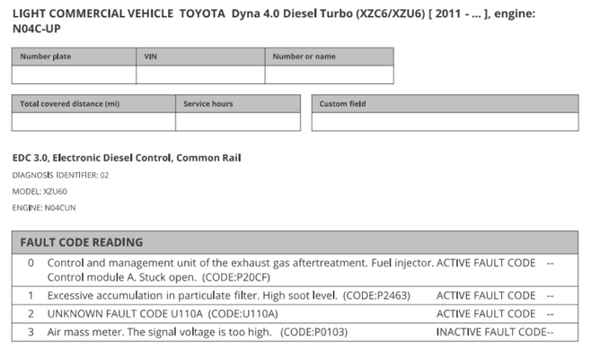
The workshop had a Jaltest multibrand diagnostics kit and also an ATS 500XM scope. The workshop carried out a health report on the truck and the following report was shared with the support team.
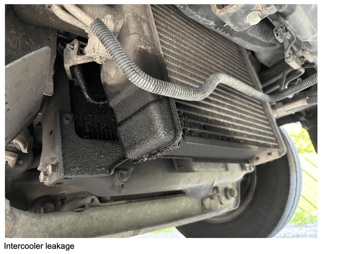
We decided to start with the air mass sensor issue as it has a major effect on engine performance and fuelling. It is a key input to the engine management unit. We looked into live data and could see the reading in grams per second was about what we expected on the idling engine. Next step was to inspect the air intake system for leaks/restrictions.
It did not take long to find oil seeping out from the turbo air intercooler. It had been leaking so badly that the engine cooling system radiator, mounted directly behind the air cooler, was badly contaminated by engine oil mixed with the escaping intake air.
Any air leak downstream of the air mass sensor alters the calculated air fuel ratio resulting in excessive soot production, reduced engine power and filling the DPF rapidly.
A new intercooler was fitted and the cooling system radiator cleaned of oil contamination. Now we had to deal with a DPF that would not regenerate.
Another scan was carried out and fault codes for air mass meter cleared. Air mass sensor fault sorted.
Fault code P20CF for control and management of the exhaust regeneration injector needed addressing next. This injector is mounted in the exhaust pipe upstream of the catalytic converter/particulate filter system. Its purpose is to inject diesel into the hot cat igniting the fuel during regen and burn out the soot trapped in the DPF monolith ceramic structure. Exhaust gas can pass through the filter but the larger particles of soot are trapped and unable to pass through the small pores in the DPF ceramic. The trapped soot builds up and increases flow resistance which is measured by the pressure differential sensor. Once a set pressure level is reached a regeneration is commanded. Regens are also carried out automatically by the engine control unit while driving under suitable conditions such as at constant highway speeds when the exhaust system is hot enough.
For a forced regeneration to be required there is something wrong in our engine system. Alternatively a forced regen may be needed when too many short trips do not allow the required exhaust temperatures to be reached, or even when the incorrect oil is added during a top up.
Regeneration injectors mounted in exhaust systems are prone to failure and more often blockage. The heat can damage the injector itself after some time in service. Soot in the exhaust stream settles into the cavity where the injector is mounted, slowly building up as solid blockage that covers the injector nozzle. This prevents the fuel getting to the catalyst to be ignited and burn soot out of the DPF.
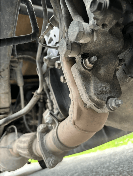
In the picture below we can see the regen injector at the front of the exhaust system.
It is cooled by the engine cooling system in an effort to control its heat stress.
The support team recommended activating the injector to test its operation and removing the housing to check for soot accumulation/blockages. However, the option of actuating the injector via the scan tool was not available on this particular control unit.
The injector housing was removed from the exhaust. It was caked solid. This would be why we cannot regenerate our DPF. While removed, the housing was fully cleaned.
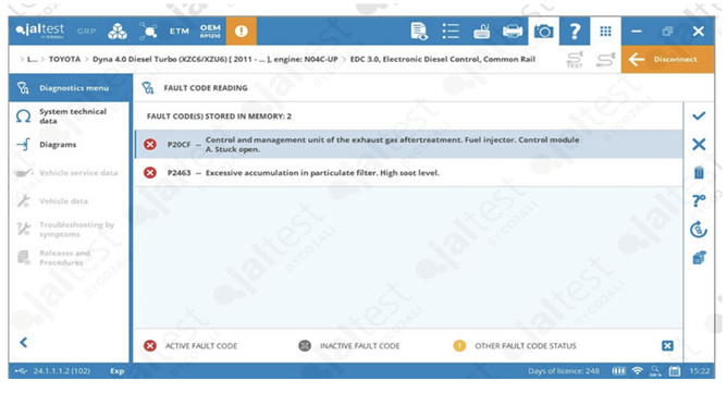
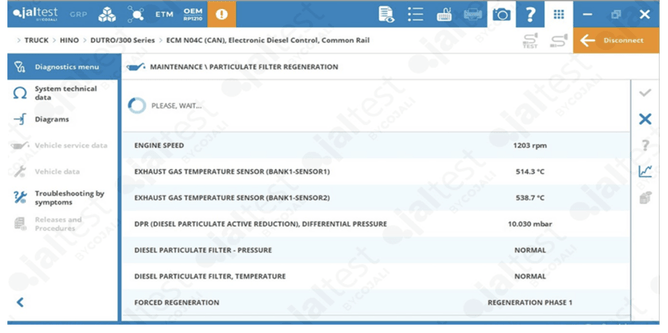
In the above Jal test scan report we can see there is an issue indicated by the P20CF fault code, either the regeneration injector circuit or the control unit itself.
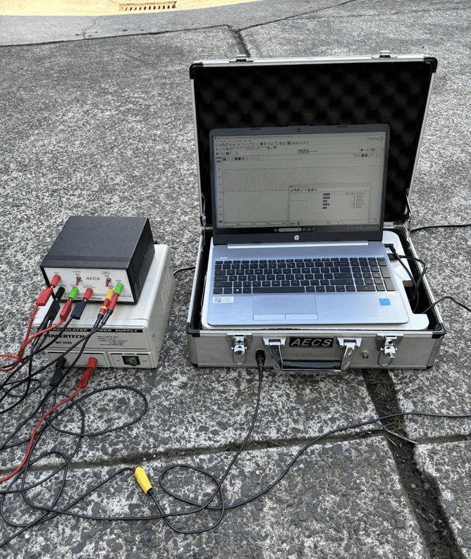
It is now time to use the ATS 500 XM scope the workshop has on site. The 500 XM is equipped with a highly accurate signal generator. With the help of an external driver box it is able to drive pretty much anything on a vehicle. Our plan was to send out a signal to our regen injector and see how it responds. Compressed air could be blown through the injector to make sure the nozzle was not blocked and the needle cavity was clear while being driven by the ATS scope's signal generator.
The plan was to drive the injector, if not blocked and it responded, for 30 minutes simulating a regen time frame while also checking for any intermittent shorts in the injector coil.
On the ATS 500 XM scope we can drive the injector via the signal generator which connects to a driver box with external power supply. With the scope's other channel we can measure the injector signal.
The scope set up is shown in the picture below. We sent out a 12/0 volt square wave signal with 50% on time , 50% off time at a frequency of 50 Hz ( 50% duration and 50 times per second). Which means our injector will be turned on & off 50 times per second and will be energised for half of a second in total or opened & closed 50 times per second.
The injector passed the flow test and 30 minute operation time with no issues.
Now the question as to why the fault code? We still have the wiring from the ECU and the ECU itself which could have an issue. Another unknown is what the prerequisites are for this fault code to be set. Is it possible that with the blocked injector cavity and soot preventing the diesel getting to the catalyst and a subsequent rise in temp sensor readings behind catalyst could trigger this fault code?
The Jaltest diagnostic system has workshop information available from the scan tool. After reading through some information on this injector fault code, Jal test mentioned the battery may need disconnecting to clear this fault code. Battery earth lead off for 2 minutes and fault for injector cleared.
It was now time to carry out a forced regen. The truck was driven for 20 minutes to get temperature up. Then the regeneration was carried out via Jal test.
10 minutes later our soot level was down.
A very pleased workshop sent the vehicle out to the driver. They had a high level of confidence that the problem was properly solved and not going to be back for the same problem anytime soon.
What causes a Toyota Dyna to require multiple DPF regenerations?
A Toyota Dyna may require multiple DPF regenerations due to various issues, including a clogged air mass sensor, air intake leaks, or a malfunctioning regeneration injector. These factors can prevent the diesel particulate filter (DPF) from reaching the necessary temperature for self-regeneration, requiring manual intervention.
How do I diagnose a blocked regeneration injector on a Toyota Dyna?
To diagnose a blocked regeneration injector, you should check for fault codes like P20CF, perform live data monitoring, and inspect the injector for soot buildup. Using diagnostic tools like the Jaltest Multibrand Diagnostics Kit and ATS 500XM scope can help test injector functionality and clear any blockages
How can the ATS 500XM scope help diagnose DPF regeneration problems?
The ATS 500XM scope is used to test and analyse components like the regeneration injector. It allows you to send signals to the injector to check for blockages, test its functionality, and ensure that it is responding correctly during a forced regeneration process. This diagnostic tool provides real-time data and accurate measurements to pinpoint issues quickly.